Services
Steel Detailing/Drafting
Steel detailing is a specialized form of engineering that involves creating detailed drawings of steel structures. These drawings are used to fabricate and erect the steel components of a building or other structure. Steel detailers use computer-aided design (CAD) software to create precise, three-dimensional models of the structure, as well as two-dimensional shop drawings that show all the necessary details for fabrication and construction. Steel detailing services may also include estimating the cost of the steel materials and labor needed for the project, coordinating with other professionals involved in the construction process, and providing technical support during the fabrication and construction phases.
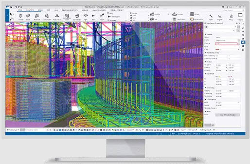
OzSteel Detailing uses Tekla Structures, the industry-standard Building Information Modelling (BIM) software, in all our projects.
Tekla Structures is widely used in the construction industry and is known for its powerful modeling capabilities and ability to handle large and complex projects. It is often used in conjunction with other construction software applications, such as scheduling and project management software.
OzSteel can provide the following:
3D Modelling
3D modeling is the process of creating a three-dimensional representation of a physical object or environment using specialized software. It involves creating a digital model of an object or environment by adding and manipulating 3D shapes and surfaces, using a computer to represent the object in a virtual space.
Shop Drawings
Shop drawings are detailed technical drawings that show how a construction project should be built. They are typically used in manufacturing and construction to help fabricate and assemble a product or building. Shop drawings include detailed information about the dimensions, materials, and construction methods for a project, and may include assembly instructions, exploded views, and other details that help ensure that the final product is built correctly and to the specified design. Shop drawings are often used in conjunction with architectural drawings and other types of technical drawings to help visualize and build a project.
Erection Plans/Drawings
Erection drawings, also known as field drawings or as-built drawings, are technical drawings that show how a structure or system should be assembled on site. They provide detailed instructions for the construction crew on how to put the various components of a building or other structure together. Erection drawings are typically created after the shop drawings and they take into account any changes or modifications that have been made to the original design during the construction process. Erection drawings may include information about the placement of components, the order in which they should be assembled, and any special tools or techniques that are needed for the assembly process. They are an important part of the construction process and help ensure that the final product is built to the correct specifications.
Fabrication Shop Drawings
Fabrication shop drawings are technical drawings that are used to show how a product or component should be fabricated or manufactured. They provide detailed information about the materials, dimensions, and construction methods that are needed to produce the final product. Fabrication shop drawings are typically used in manufacturing and construction to help fabricate and assemble a product or building.
Fabrication shop drawings may include information about the size and shape of the finished product, the type and thickness of the materials that should be used, and any special techniques or processes that are needed to fabricate the product. They may also include assembly instructions, exploded views, and other details that help ensure that the final product is built correctly and to the specified design. Fabrication shop drawings are often used in conjunction with architectural drawings and other types of technical drawings to help visualize and build a project.
Advanced Bill of Materials (BOM)
An advanced bill of materials (BOM) is a detailed list of the materials, parts, and assemblies that are required to manufacture a product. It includes information about the quantities of each item that are needed, as well as the specifications and characteristics of each item. An advanced BOM may also include information about the relationships between different parts and assemblies, as well as any alternative materials or parts that can be used.
An advanced BOM is often used in conjunction with computer-aided design (CAD) software and manufacturing execution systems (MES) to help manage and track the production process. It can be used to plan and schedule production, as well as to track and control inventory levels. An advanced BOM can also be used to identify opportunities for cost savings and efficiency improvements in the manufacturing process.
BIM Modelling and Clash Detection
Building information modeling (BIM) is a digital representation of the physical and functional characteristics of a building or other structure. It is used to design, construct, and manage buildings and other structures. BIM modeling involves creating a digital model of a building or structure using specialized software, which can include detailed information about the geometry, location, and properties of the various components of the structure.
Clash detection is a process that is used to identify and resolve conflicts or inconsistencies in the design of a building or other structure. It involves comparing different parts of the design to ensure that they do not interfere with each other or violate any design constraints. Clash detection is often performed using BIM software, which can automatically identify and flag potential conflicts in the design. It is an important part of the construction process and helps ensure that the final product is built to the correct specifications.
DSTV Files
Tekla Structures produces NC files in DSTV format. DSTV format is an industrial standard defined by the German Steel Construction Association (Deutsche Stahlbau-Verband). A DSTV file is a text file in ASCII format. In most cases, each part has its own DSTV file.
DXF Files
DXF (Drawing Exchange Format) is a file format that was developed by AutoDesk for the exchange of data between AutoCAD and other software applications. It is a widely used format for storing technical drawings, including architectural, engineering, and construction drawings.
DXF files contain information about the geometric shapes, lines, and text that make up a technical drawing, as well as metadata about the drawing, such as the units of measurement, scale, and layer information. DXF files can be opened and edited using a variety of computer-aided design (CAD) software applications, including AutoCAD, SketchUp, and others.
DXF files are often used to exchange technical drawings between different software applications, as they can be easily imported and exported by many different types of software. They are an important part of the design and construction process, as they help ensure that the final product is built to the correct specifications.
Specialist Reports
Specialist reports are detailed written documents that provide information and analysis on a specific topic or subject.
OzSteel can provide Material list reports, Assembly Reports, Parts Lists, Purlin/Girt, Purlin Accessories, Bolt Summary, Assembly Bolt lists, etc.
Field Bolt lists
A field bolt list is a document that specifies the types, quantities, and locations of bolts that are needed for a construction project. It is typically used to help ensure that all of the necessary bolts are available on-site and that they are installed in the correct locations.
A field bolt list may include information about the size, material, and finish of the bolts, as well as their thread type and any special requirements or specifications that must be followed. It may also include information about the locations where the bolts will be used, such as the specific beams, columns, or other structural elements where they will be installed.
Field bolt lists are an important part of the construction process, as they help ensure that all of the necessary bolts are available and that they are installed correctly. They are typically used in conjunction with other technical drawings and construction documents to help visualize and build a project.
Talk to us about other requirements that you may need in your projects.